Data Flow Diagram (DFD)
DATA FLOW DIAGRAM
Data
Flow Diagram (DFD) describes the system distribution into a smaller
system. DFD allows the user to easily learn about computer and
understand about worked system. DFD allows to learn new system are
logically develop without consider the physically environment where the
data flow (like by phone, mail, etc) or physically environment where the
will be save (like file card, microfiche, hard disk, tape, diskette,
etc). DFD is a tool used in methodology structured Analysis and design.
CONTEXT DIAGRAM
Context
Diagram consists of one process to describe the system environment.
It’s a highest level in DFD which is describes all the input into the
system and output from system. System has a boundary which is to
separate the system with the external entity. In context diagram there
is no storage. Because context diagram are process to describe the
system environment.
ZERO DIAGRAMS
Zero
diagrams are describes the process of DFD. It gives a opinion spread
all over the handled system, indicate the function or main process, data
flow and external entity. This level enabled the data storage.
For
no specific process in next level then add symbol ‘*’ or ‘P’ in the end
of process. Balancing of input and output between Zero Diagram with
Context Diagram always maintenance.
DETAIL DIAGRAMS
Detail Diagram is diagram which is explaining what kind of process in the zero diagrams or on the top level.
Numbering level in DFD:
Level Name
|
Diagram Name
|
Process Number
|
0
|
Context Diagram
|
-
|
1
|
Zero Diagram
|
1.0, 2.0, 3.0, …
|
2
|
Diagram 1.0
|
1.1, 1.2, 1.3, …
|
3
|
Diagram 1.1
|
1.1.1, 1.1.2, …
|
In one level at least seven processes and maximal nine process, if more than nine it must decomposition.
PROCESS SPECIFICATION
Each
process in DFD must have process specification. Method in top level use
to describe process with descriptive words. In detailed level that is
lower process (functional primitive) need more structural specification.
Process
specification will be a manual to programmer in create program or
coding. Method in process specification is process scatter into story
type, decision table, and decision tree.
EXTERNAL ENTITY
External
Entity is entity in outside system environment which is like people,
organization or others system in outside environment will give input or
receive output from systems. External entity is uncounted part of the
system. It symbolize with box notation.

Picture1. External Entity Notation
External entity can give identification with small letter in left top corner like bellow:

external entity example
- Terminal name are noun words
- Terminal never have same name except the object are same.
DATA FLOW
Data
Flow is place to flow the information. Describe with straight line that
connected all the component of the system. Data flow showing with arrow
and given name line or data flow.
This
data flow stream between process, data store, and external entity and
showing data flow can be input for the system or output system.

Picture2. Data flows are flow from consumer external entity into process of consumer orders it called consumer orders.
Guidelines to give a name:
- Data flow name consist of few flow words are connected with a line.
- No same of naming and the name should reflect its content.
- Data flow consists of few elements called element group.
- Avoid using word ‘data’ or ‘information’ to give a name in data flow.
- Possibly when write data flow name must complete write.
Other provisions:
- Data flow name put into a process may not be same as the data flow out of the process.
- Data flow are in or out from the data storage may not give name if:
o Simple data flow and easy to know.
o Data flow describes the entire data item.
- There
is no data flow from terminal into data storage or the other way
because terminal is not of part the system, connection between terminal
and data storage must passed with process.
PROCESS
Process
is activity or what is system do. Process can process the input data
into output data. Process has a function to transformation one ore
several input data into one or several output agree with the
specification. Each process has one or several input along with creating
one or several output. Process may be called bubble.
Physical
Data Flow Diagram (PDFD), process can create by person, machine or
computer. Logical Data Flow Diagram (LDFD) is a process just show
process from computer.
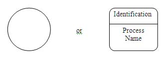
Process Notation:

Picture3. Process notation in DFD
Guidelines to give a name:
- Process name consist of verbs an noun which reflects the function of the process.
- Never use word ‘processes’ as a part of name certain bubble.
- There are no several processes which have a same name.
- Process
must have number. Numbering order possibility follow the flow or
process orders, however numbering order means not absolutely as
chronology process order.
DATA STORAGE
Data
storage is place to store data on the system. Symbolize with a pair of
horizontal parallel line with one of the side are opened. Process can
take data from or give data into database.
Symbol of data storage:

Picture4. Data storage symbol.
Guidelines to give a name:
- Name must reflect the data storage
- If name more than one word then must give underscore.
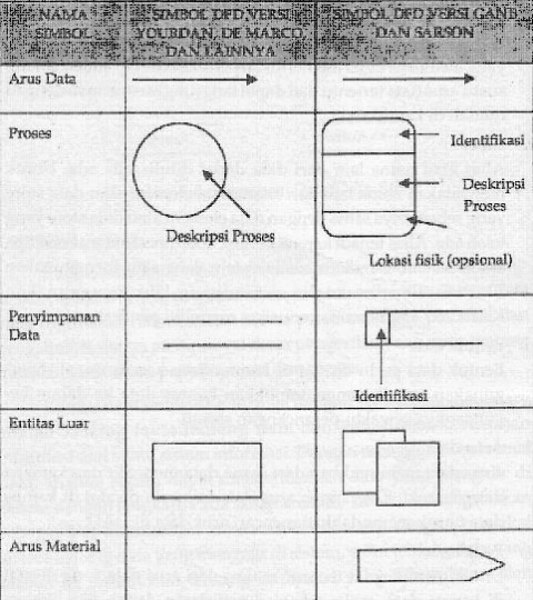
DFD SYMBOLS


DATA DICTIONARY
Data
Dictionary (DD) use to help system subject to define application detail
and organize the entire data element which system use precisely until
user and system analyst has same base interpretation about input,
output, store and process. In analyst stage, dictionary data use as
communication tools between system analysts with user. In system plan
stage, dictionary data use to plan input, report, and database. Data
flow in DFD are global, more detailed information seen on dictionary
data.
Dictionary data contains:
- Data flow name: must write in order to all the reader who need more explanation about data flow can search easily.
- Alias: alias or other name from data can be written if the data are used.
- Data form: use to categorize dictionary data into application when system plans.
- Data flow: show from where data flow and where data goes.
- Explanation: give explanation about meaning from data flow.
DFD BALANCING
Data
flow which enter into and out from one process must same with data flow
which enter into and out from detailed process in lower level. Data
flow name which enter into and out from one process must same as data
flow name which enter into and out from detailed process. Amount and
external entity name from certain process must same with amount and
external entity name from that detail process.
The issues that must be considered in the DFD which have more than one level:
- Must have balance input and output between one level and next level.
- Balance
between level 0 and level 1 seen in input or output from data flow go
or from terminal in level 0, while balance between level 1 and level 2
seen in input or output from data flow go or from process concerned.
- Data flow name, data storage and terminal each level must same if the object same.
PROHIBITION IN DFD
- Data flow may not from external entity direct to external entity without through a process.
- Data flow may not from data storage direct to external entity without through a process.
- Data flow may not from data storage direct to other data storage without through a process.
- Data flow from one process direct to other process without through a saving data should or be avoided as much as possible.
EXAMPLE
Precision
Tools sells a line of high-quality woodworking tools. When customers
place orders on the company’s Web site, the system checks to see if the
items are in stock, issues a status message to the customer, and
generates a shipping order to the warehouse, which fills the order. When
the order is shipped, the customer is billed. The system also produces
various reports.
- Draw a context diagram for the order system
- Draw DFD diagram 0 for the order system
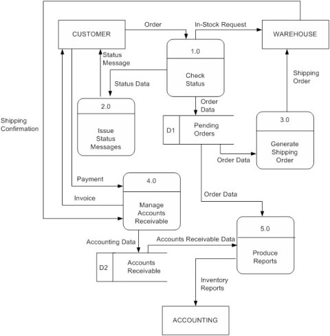
First we must identify Entities, Process, Data Stores, and Data Flow
* Entities
- Customer
- Warehouse
- Accounting
* Processes
- 1.0 Check Status
- 2.0 Issue Status Messages
- 3.0 Generate Shipping Order
- 4.0 Manage Accounts Receivable
- 5.0 Produce Reports
* Data Stores
- D1 Pending Orders
- D2 Accounts Receivable
* Data Flows
** 1.0
– Order
– In-Stock Request
– Order Data
– In-Stock Request
– Order Data
** 2.0
- Status Data
- Status Message
– Shipping Order
– Order Data
**4.0
- Invoice
- Shipping Confirmation
- Payment
- Accounting Data** 5.0
- Accounts Receivable Data
- Order Data
- Inventory Reports
Then draw Context Diagram of Order System

And draw Level-0 of Order System

There are several common modeling rules when creating DFDs:
-
All processes must have at least one data flow in and one data flow out.
-
All processes should modify the incoming data, producing new forms of outgoing data.
-
Each data store must be involved with at least one data flow.
-
Each external entity must be involved with at least one data flow.
-
A data flow must be attached to at least one process.
reference : http://gedesanjaya.wordpress.com/2009/04/03/analysis-and-design-information-system-part-v/

You can find more data flow diagram examples and templates in creately diagram community.
ReplyDeleteAdupconromp_ne Kelly Campos https://wakelet.com/wake/dDXb8fTu2fyyYz7x5Zeqj
ReplyDeleteulmicootu
0tempcenVcizu Nikki Marie download
ReplyDeletedownload
click
link
clinlatabmarg
Mmurecperra Jensen Alfonso Download
ReplyDeleteNetBalancer
ESET NOD32 Smart Security
nodenkirchvab